- Description
- Technical Data
- Equipment: Base / Base addition
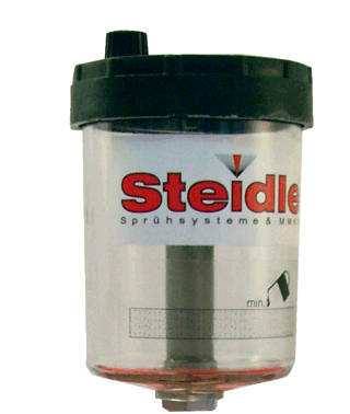
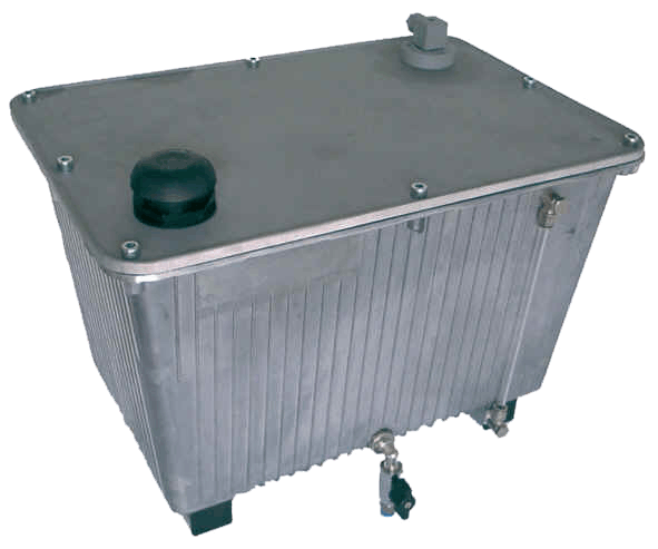
- Equipment: Reservoir
- Equipment: Drive
- Equipment: Feed tube
- Equipment: Nozzle
- Equipment: Option
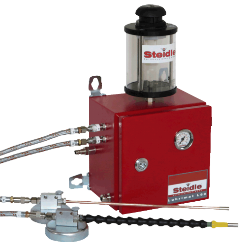
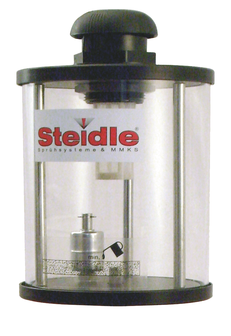
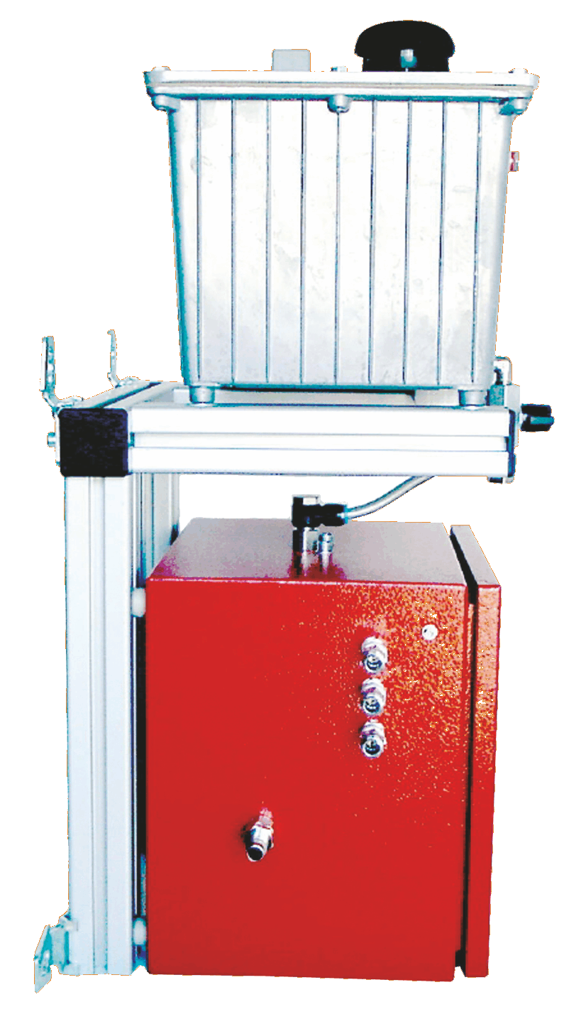
Piston pump system for spraying the smallest quantities of liquid.
Main application range:
External MQL in all metal-cutting operations. Pinpoint or small area lubrication in chipless forming operations. Application of mould release and anti-corrosion agents or other spray-on substances.
Operating principle:
The liquid flows from the reservoir into a piston pump. This pushes an exact quantity of the lubricant into the internal feed tube. Separately supplied compressed air splits the medium at the nozzle tip and sprays it.
Adjustability
-
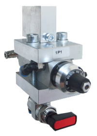
Swept volume of the pump (manual)
-
Clock frequency of the pump (manual)
-
Quantity of spray air (manual)
-
Spray air pressure (manual)
-
Switch on/off using actuation control drive (electric, pneumatic or manual)
| Term | Figure | Unit |
|---|---|---|
| Operating pressure | 4 - 8 | bar |
| Liquid flowrate | 0-150* | ml/h per nozzle |
| Typical consumption | 10-20* | ml/h per nozzle |
| Lubricoolant | Lubrimax® and other | |
| Recommended viscosity | 1 - 100* | mm²/s (at 40°C) |
| Dimensions | HxWxD (mm) | |
|---|---|---|
| Housing** (without reservoir) | 200x200x155 | |
| 300x300x210 | ||
| 400x400x210 | ||
| special size | ||
– All pumps are standard synchronous drive. Separate drive, if required (all pumps individually or certain groups). The use of the logic panel enables all pumps to be operated using only one frequency generator./font>
– Ventilation unit integrated underneath the pump module.
– Frequency generator for pump pulses, manually adjustable 0 – 90 stroke min-1.
– A dedicated air valve for each nozzle, to enable the quantity of spray air to be adjusted.
– Pressure reducing valve to set spray air pressure. It also equalizes pressure variations in the supply tube and the system and ensures that the spray profile is even.
– Manometer (0 – 10 bar) in front of door to display spray air pressure. – Coupler plug NG8 for compressed air supply to left side of housing.
– Air filter with integrated water separator and drainage opening on housing underside.
– High-grade push in/screw fittings/ pneumatic tubes.
– Stable, compact metal housing (200x200x155, 300x300x210, or 400x400x210) with robust metal closer and door seal for dust protection and noise reduction, earthing pin.
– Component labelling in accordance with the designations in the pneumatic connection diagram.
– Numbering clips on every liquid conduit.
Housing assembly
Wall installation
– Solenoid valve 3/2 way (up to 3 nozzles 120 Nl/min, 4 nozzles and over 1300 NL/min with auxiliary actuation (for occasional manual switching on/off). Coil with plug in 24V DC, 24V AC, 110V AC or 230V AC. Cable bushing on left side of housing. In the case of separate actuation control device, each pump (or group of pumps) is controlled via a dedicated solenoid valve.
– Pneumatic valve 3/2 way (up to 3 nozzles 550 Nl/min, 4 nozzles and over 1300 NL/min. With push in connection ø4 for control air on left outer side of housing.
– Hand valve 3/2 way (600 Nl/min) as valve rocker on right outer side of housing.
– Mechanical valves 3/2 way (700Nl/min) as plunger, roller lever or knee roller lever in versions NC or NO. Delivered with the corresponding connectors and a 2m tube PUNØ8 to the unit.
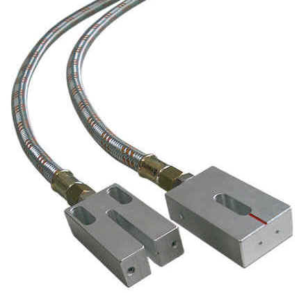
– Coaxial feed tube with EASY-COAX® system. Outer tube of strong rubber construction with robust metal sleeve Ø11, inner tube for delivery of medium, constructed of long-life PTFE Ø3. Smallest bending radius 50 mm. Standard length 3,000, non-standard lengths up to 20,000 available on request.
– Numbering clips on feed tube for easy assignment of pumps and nozzles.
– 4 x round magnet Ø80 (mounted on the reverse side) for easy installation of the housing.
– 4 x mounting straps (mounted on the reverse side) for fixed installation of the housing


